Archive for November, 2012
Halloween – traffic light costume
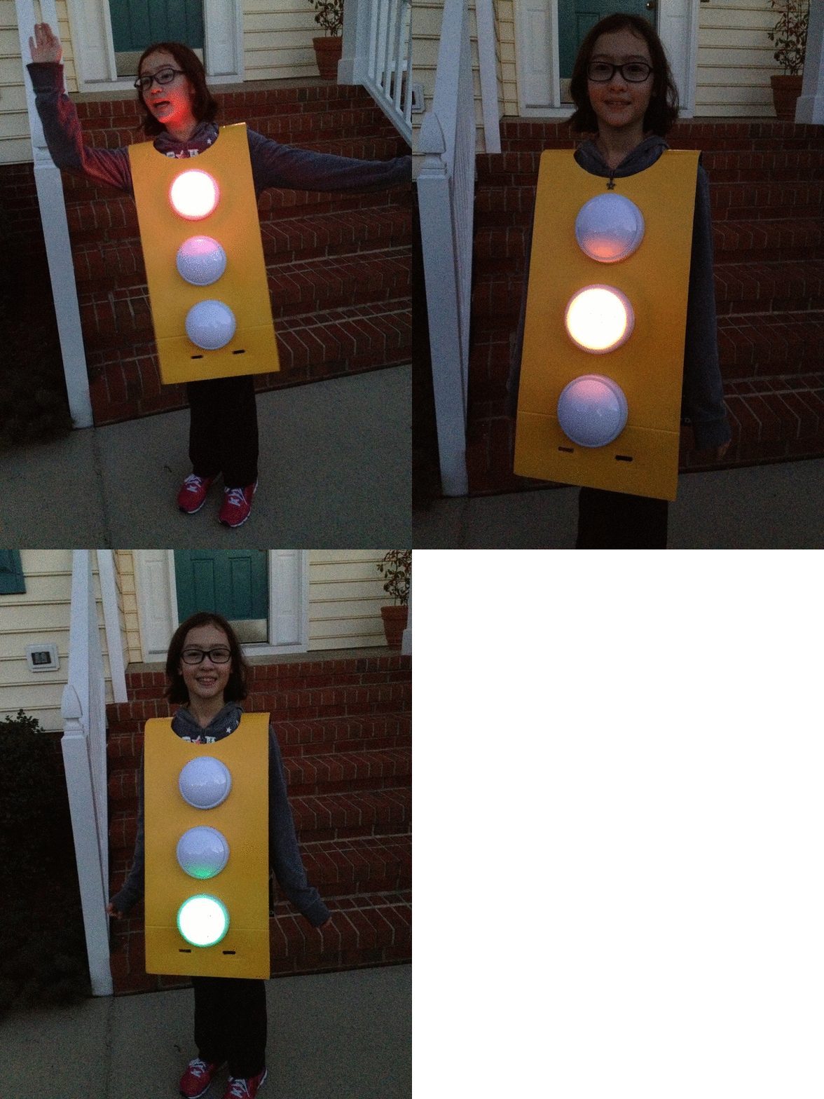
0Last year, at the neighborhood Halloween party, one of the kids had dressed up as a traffic light. He simply wore all black, and he had three cardboard circles attached to his front. Audrey saw that boy’s costume and got to thinking… could we build one with real lights?
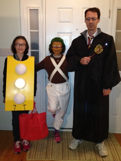
This is what we came up with.
Putting it together
We had the entire year to think about it. Sometime in the summer, we actually started planning. I knew that we could do the controls, but I was not so confident about the power or how to drive several LEDs.
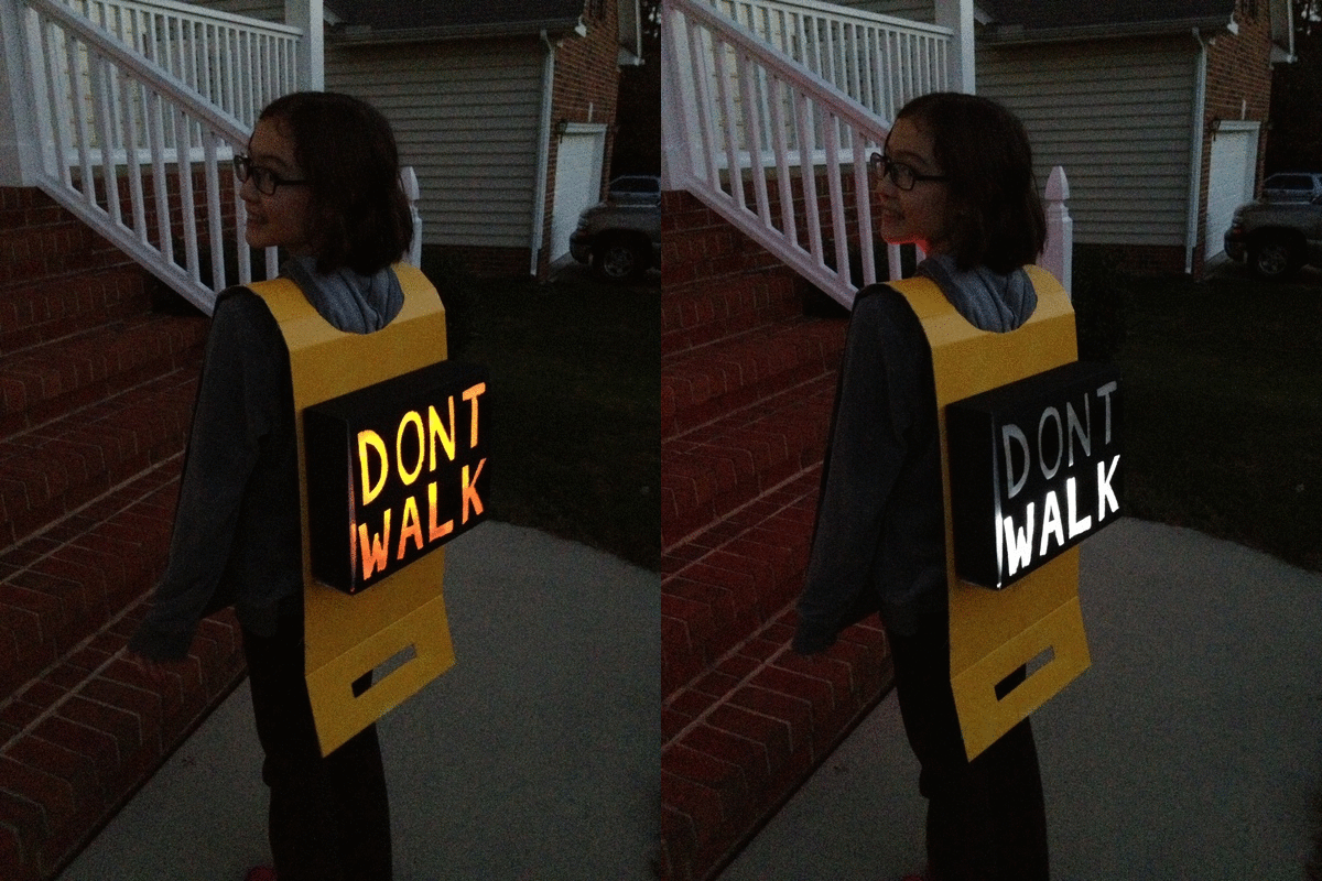
The controller was easy. We have been using Arduinos for several projects, and I had ordered a few “nano” boards, which are about the size of a stick of gum. We plugged one into a solderless prototyping board. We used five of the Arduino’s outputs for our five lights: red, yellow, green, “WALK” (white) and “DONT WALK” (orange). We ordered super-bright colored LEDs from DealExtreme in Hong Kong.
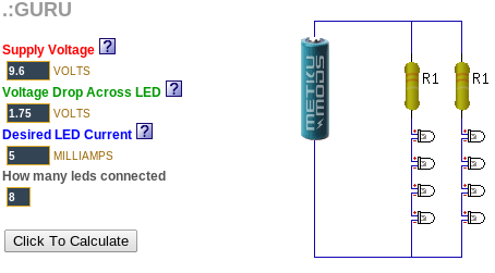
The hard part was figuring out how to power several LEDs at the same time. I discovered a web site called “ledcalc.com” that showed us how to arrange the LEDs in several serial strings wired to each other in parallel. And after taking a few measurements, we figure out what the voltage drop on each LED was and we estimated how much current to push through each LED. This suggested that we should use a higher voltage than I normally would use to just power the Arduino. We chose 8 NiMH rechargeable AA batteries for 9.6 volts.
The LED calculator suggested that for red, yellow and orange, we should plug the LEDs in strings of 4 with a small resistor at the end. We wanted 8 LEDs for each color, so that meant we’d plug two strings of 4 LEDs together in parallel.
Since the “forward voltage” (voltage drop) across the white and green LEDs was higher, we ended up using strings of 3 LEDs for those. Fortunately, they were so bright that the fewer LEDs made no difference in overall brightness.
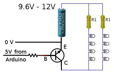
Now came the tricky part. We wanted the LEDs to run at 9.6 volts, but the Arduino runs at 5 volts. That meant we needed to use a transistor on each output to switch the higher-voltage LED strings on and off. We were able to figure out how to do this by looking at an Arduino experiment book. Below, you can see how one 5V output line from the Arduino can be used to switch 9.6V through a bank of LEDs.
During our tests, we found that after a while (a pretty long while), the white and green LEDs got very dim while the others stayed normal brightness. We decided that the battery had drained and the voltage had dropped just enough to make driving the three higher-voltage LEDs too hard. Doing a little bit of back-of-the-napkin math tells why. The white and green LEDs each have a 2.5V drop… times three LEDs and that means you have to have at least 7.5V to run them at all in series. The other color LEDs each dropped 1.75V, for a total of 7.0V. That means the white and green lights will poop out 0.5V earlier than the other colors will.
As a quick fix, we replaced the 1.2 volt NiMH rechargeable batteries with 1.5 volt alkaline batteries, making our total supply voltage a bit higher, a full 12 volts. This kept all of the LEDs bright all night. A quick estimate suggested we might get two or more DAYS worth of operation from a single set of batteries. But after watching them dim earlier, I decided to take a spare set of batteries with us while we went trick-or-treating, and I kept a close eye on the white and green LED brightness.
The big night
Halloween was a big hit. Everyone got a chuckle out of the costume, especially when Audrey turned around and they could see the WALK and DONT WALK signs.
Here is a photo of the Audrey in her stop light costume, Syndey as an Oompa Loompa and me as Harry Potter.
The Happy Crabby
0In 2009, we got a hermit crab named “Peek-a-boo”. We kept him in a plastic shoebox-sized container with creek sand in the bottom and holes drilled in the lid. He seemed to enjoy his new home, and we enjoyed his company. But some time in the winter, he died.
This turned into an annual tradition. Peek-a-boo was followed by Boo and Sprinkle in 2010, Flicker in 2011, and Blink and Barney in 2012. Some of our crabs only stayed with us a short while; others lived through the winter, but not much longer.
I wanted to know how we could take better care of them, so in 2011, we replaced the plastic box with a small glass terrarium with a glass lid. I suspected that they were getting too cold in the winter, but when I read about crabs, I found that humidity might have been a factor. I know our house gets very dry in the winter.
It was time to find measure the temperature and humidity inside the cage.
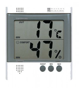
I thought about buying a simple hygrometer. We have one in our hallway . But I wanted to keep a long-running log of temperature and humidity over time.
So I decided to build an Arduino-based crab cage monitor.
The Happy Crabby
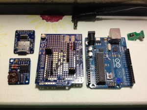
I would use an Arduino UNO to control the overall flow. I wanted to add the following peripherals:
- temperature/humidity sensor – I chose one based on the SHT11 sensor: see Adafruit or the one I got.
- real-time clock – Adafruit has a breakout board for $9.
- SD card slot – Adafruit has a breakout board for $15.
- LCD display – Adafruit has a 20×4 character LCD for $18 and an I2C-to-LCD driver board for $10.
- Relays to turn on/off a heater or light – I have not added this yet.
- Some buttons for a simple UI – I have not added this yet.
Drivers
The first thing I had to do was write some software to read the temperature and humidity from the SHT11 board. The documentation claimed that it was an I2C device, which should have made it very easy. I knew all about I2C from when I worked at Ericsson. A lot of peripherals used an I2C interface. It’s a simple two-wire protocol where you can just wiggle two output lines in a specific order to send signals to the devices. It turns out that the SHT11 is mostly I2C, but it has a strange quirk that I had to code around.
Hardware Planning
After I was receiving real temperature and humidity readings from the SHT11, I had to start allocating Arduino I/O pins to the peripherals. I made a spreadsheet to keep track of the pins. Some pins on the Arduino have special alternate uses, so I made a note of them there. Since I was working on a prototyping board, I kept changing stuff, and when I did I’d just create a new spreadsheet column. In some configurations, I did not have enough pins… specifically, if I did not use the I2C-to-LCD board, I had to allocate most of my pins to simply driving the LCD display. In other configurations, I had plenty of pins left over.
What I ended up with was this:
| PIN | FEATURES | MY USE |
|---|---|---|
| D0 | RX | serial (future: for Bluetooth) |
| D1 | TX | serial (future: for Bluetooth) |
| D2 | relay (future: to control a relay) | |
| D3 | PWM | |
| D4 | ||
| D5 | PWM | |
| D6 | PWM | |
| D7 | ||
| D8 | bit-banged I2C-SDA for T/H | |
| D9 | PWM | bit-banged I2C-SCK for T/H |
| D10 | PWM or SPI-SS | SPI-SS for SD card |
| D11 | PWM or SPI-MOSI | SPI-MOSI for SD card |
| D12 | SPI-MISO | SPI-MISO for SD card |
| D13 | LED, SPI-SCK | SPI-SCK for SD card |
| A0 | (future) keyboard | |
| A1 | ||
| A2 | ||
| A3 | ||
| A4 | SDA | I2C-SDA for RTC and LCD |
| A5 | SCK | I2C-SCK for RTC and LCD |
Software and Integration
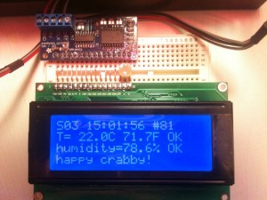
I wrote a simple program that takes a temperature and humidity reading, reads the current time, appends a line to a CSV file on the SD card, and updates the LCD display. Then it sleeps for a minute and does it all over again.
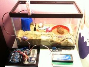
For a long while, we ran the Happy Crabby on the prototype board, with wires hanging out all over.
What we learned
We ran in this configuration for a long time. We had been thinking that we would eventually add a relay to control either a heat lamp or a terrarium heater pad. But after taking measurements for several months, we decided that temperature was nearly as much of a problem in our house as humidity.
So we kept an eye on the humidity and we rearranged the inside of the cage, dumping a few inches of moist sand into the bottom. They like to dig tunnels and hide, especially when they are molting. Overall, they seem to be healthier now that the cage is not so dry, and they are less stressed because they have a place to hide.
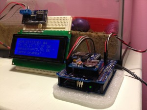
Almost a year after we originally started taking measurements, we decided that our design was OK enough to make “permanent”. So we bought a “shield” board and soldered all of the pieces down. I made sure that all of the pieces still plug together, in case we feel like changing it down the road. It looks a little nicer without all of the rats nest of wires, and it’s a lot less likely to get messed up if somebody bumps it.
Resources
Source code that we wrote for this project can be found on github.
